Description
MITSUBISHI inverter repair
Failure phenomenon: the boot operation shows OC alarm
Failure analysis: MITSUBISHI inverter fault phenomenon caused by the main reason for the following may be OC:
(1) driving circuit aging due to the use of longer life, will inevitably lead to the aging of the components, so as to cause the drive waveform distortion, the output voltage is not stable, so often a run on the OC alarm.
(2) the IPM module can also cause damage to the OC alarm power module use D700 series of MITSUBISHI inverter not only contains overcurrent, undervoltage detection circuit, but also include amplifying and driving circuit, so whether it is the damage detection circuit, driving circuit and high power damage, damage to the transistor are likely to cause OC alarm.
(3) most of the failure causes are caused by the failure of the thick film of the switching power supply.
(4) ERR fault is an under voltage fault, usually because of the voltage detection circuit resistance or connection problems and lead to the generation of the fault, rather than the actual input voltage is really the emergence of under voltage. Most of the F700 series of OC fault is caused by damage to the drive circuit, the drive circuit which has a ceramic thick film circuit package, which brings some difficulties to the maintenance, the thick film circuit is mainly designed a driver circuit based on.
(5) we will encounter some LV fault, there is less pressure fault mostly because of the bus detection circuit malfunction, MITSUBISHI inverter also designed a circuit for voltage and current detection. A common fault of power switch pulse transformer is damaged F700 series inverter, due to the short circuit output switching power supply load, abrupt or bus voltage caused pulse transformer‘s primary and secondary winding damage.
Repair: disassemble found part of the normal voltage power supply board, after inspection found the driving circuit has an output is not normal, remove the check after the discovery of optocoupler has been bad, the IGBT module is normal, to eliminate the fault in the replacement of these accessories.
MITSUBISHI inverter common fault code and troubleshooting
E.UVT fault under voltage protection
Failure Description: if the inverter power supply voltage drop, the control loop may not play a normal function. Or cause the motor torque is insufficient, the increase of heating. To this end, when the power supply voltage drops below 300V, the output of the inverter is stopped. If P, there is no short circuit between P1, then under voltage protection function action.
Troubleshooting: according to the fault interpretation, there are 2 places where the fault occurs.
First: when the main circuit of the power supply voltage down to 300V, or P, there is no short circuit between P1, resulting in the inverter internal DC bus voltage is low, showing the UVT fault.
Second: when the inverter internal DC bus voltage is normal, but the detection circuit damage, it will show the UVT fault. The DC voltage detection in direct step-down mode after sampling, enter the optocoupler isolation, after entering the CPU. In maintenance, will find the optocoupler will often be damaged, you can repair replacement of optocoupler.
E.GF fault output side ground fault over current protection
Fault description: when the inverter output side (load side) of the grounding, through the grounding current, the inverter output.
Troubleshooting: according to the fault of the explanation, the failure point is mainly in 2 aspects.
The first: the output of the motor side to the ground short circuit, when there is current output, the frequency converter detects the three-phase current and is not zero, the inverter stop output, display the ground fault.
Second: inverter internal current detection fault. The current detection circuit is after Holzer detection and sampling, into the control card processing. Maintenance as long as the first detection of Holzer components, if the Holzer component is a good case, you can change the control card, you can basically solve the problem.
E.OC1, OC2, OC3 fault acceleration, constant speed, deceleration in the over current fault.
Fault description: when in the acceleration, constant speed, deceleration process, when the inverter output current exceeds 200% of the rated current, the protection circuit action, stop inverter output.
Trouble shooting:
First: the load is a sharp change, or the load is too heavy.
Second: output is short circuit, including the motor side there is no short circuit, if the motor side is not short circuit, then the inverter output is short circuit?
Third: inverter internal hardware failure, including current detection, IGBT module, drive circuit damage, etc.. These problems will be gradually eliminated, the first to test the IGBT module, after the test drive circuit, and then detect the current detection part of the line. These are problems that are often encountered in maintenance.
E6, E7 fault CPU fault
Fault description: if the built-in CPU arithmetic operations in the loop is not over the scheduled time, the inverter test to determine the exception, the inverter output.
Troubleshooting: there is such a failure to detect the connection between the control card and the power card is firm. If the line is not a problem, then it is likely to be
1, the power card on the integrated circuit 1302 H02 damage.
2, the power card isolation optocoupler damage and CPU damage. The probability of such failure CPU damage is relatively large.
E.LF fault output under phase protection
Fault description: when the inverter output side (load side) three phase (U, V, W) in a phase off, the inverter output.
Trouble shooting:
1, testing the motor side wiring is normal, if the normal is the problem of the inverter.
2, inverter missing phase, check the inverter output voltage is balanced. If the output voltage is balanced, then the current detection problems. Check Holzer components and output status detection circuit. You can find a problem.
Jia Hong Wei maintenance services
.jpg)
.jpg)

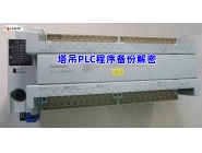 Backup and decryption of tower crane PLC program
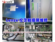 Lenz touch screen repair
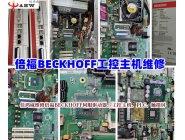 BECKHOFF industrial control host maintenance
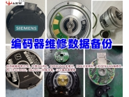 Encoder maintenance data backup
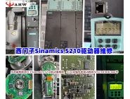 Sinamics S210 driver maintenance
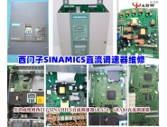 SIEMENS DC governor maintenance
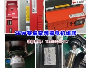 SEW Saiwei inverter maintenance
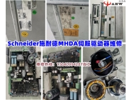 Schneider MHDA servo driver maintenance
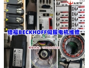 Beckhoff servo motor maintenance
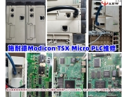 Schneider Modicon TSX Micro PLC maintenance